18 September 2019
Security research: CODESYS Runtime, a PLC control framework. Part 2
- The framework
- CODESYS Runtime: description of the object of research
- Information from public sources
- Investigating the CODESYS PDU protocol stack
- Detected vulnerabilities and potential attacks
- Description of the testing bench
- Attacks at the Datagram layer
- Vulnerability in the channel layer. Predictability of the channel ID
- Vulnerabilities of the Services layer
- In conclusion
Investigating the CODESYS PDU protocol stack
This chapter is devoted to investigating the stack of protocols of CODESYS PDU (Packet Data Unit). This protocol stack is used for communication between CODESYS network nodes, including CODESYS Development System and CODESYS Runtime.
The CODESYS PDU protocol stack is based on the ISO/OSI model. Like the ISO/OSI model, each layer in the CODESYS PDU protocol is responsible for its own area of operations. To fully understand the operations of the CODESYS PDU protocol, each of its layers must be studied in detail.
Note: The CODESYS PDU protocol stack was investigated using the “black box” method, so most of the names of fields and layers used herein are based on their purpose. Therefore, the names used in the subsequent description may differ from those that are used in public documentation or that were termed by other researchers.
For example, in one of the researched documents, the following names are used for various layers of the CODESYS PDU protocol:
- For the first layer: “datagram layer”, “Layer 2” or “block driver” (hereinafter referred to as the Block Driver layer)
- For the second layer: “network layer”, “Layer 3” or “router” (hereinafter referred to as the Datagram layer)
- For the third layer: “protocol layer”, “Layer 4” or “channel management” (hereinafter referred to as the Channel layer)
- For the fourth layer: “application layer”, “layer 7” or “application services” (hereinafter referred to as the Services layer)
Basic description of the protocol
CODESYS PDU (Packet Data Unit) is a protocol stack consisting of four different layers:
- Block Driver layer
- Datagram layer
- Channel layer
- Services layer
The order of bytes in this protocol stack is little endian, but can be changed to big endian if necessary. Protocol operation is synchronous or asynchronous depending on the protocol layer.
Use of the CODESYS PDU protocol is not limited to network communication. It is also used for communication over USB, the CAN bus, and serial ports. The CODESYS Runtime environment always uses the capabilities of the operating system for which it was adapted. Therefore, the resultant information packet will contain the generated data of CODESYS Runtime and the data generated by OS drivers for the specific physical interface.
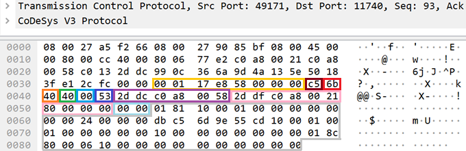
For example, the resultant CODESYS PDU packet sent through a network interface over TCP will contain two protocol stacks: TCP and CODESYS PDU.
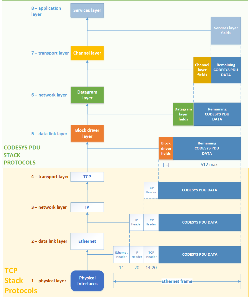
Example use of the TCP and CODESYS PDU protocol stacks in one packet
The capability for communication over physical interfaces is implemented by components of the Communication – Block Drivers group. In addition, any developer may develop their own Block Driver and use the CODESYS PDU protocol within it.
This protocol is based on the ISO/OSI model. CODESYS PDU fully excluded the physical layer from this model, and the session layer and presentation layer were merged with the application layer. Each specific layer is processed by one component or multiple components from one group.
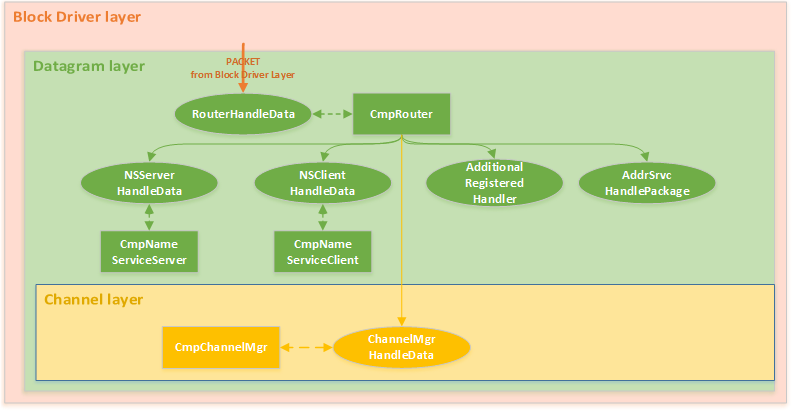
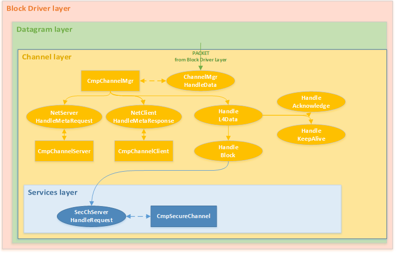
Below is a schematic representation of how components are involved in parsing an inbound packet generated based on the CODESYS PDU protocol.
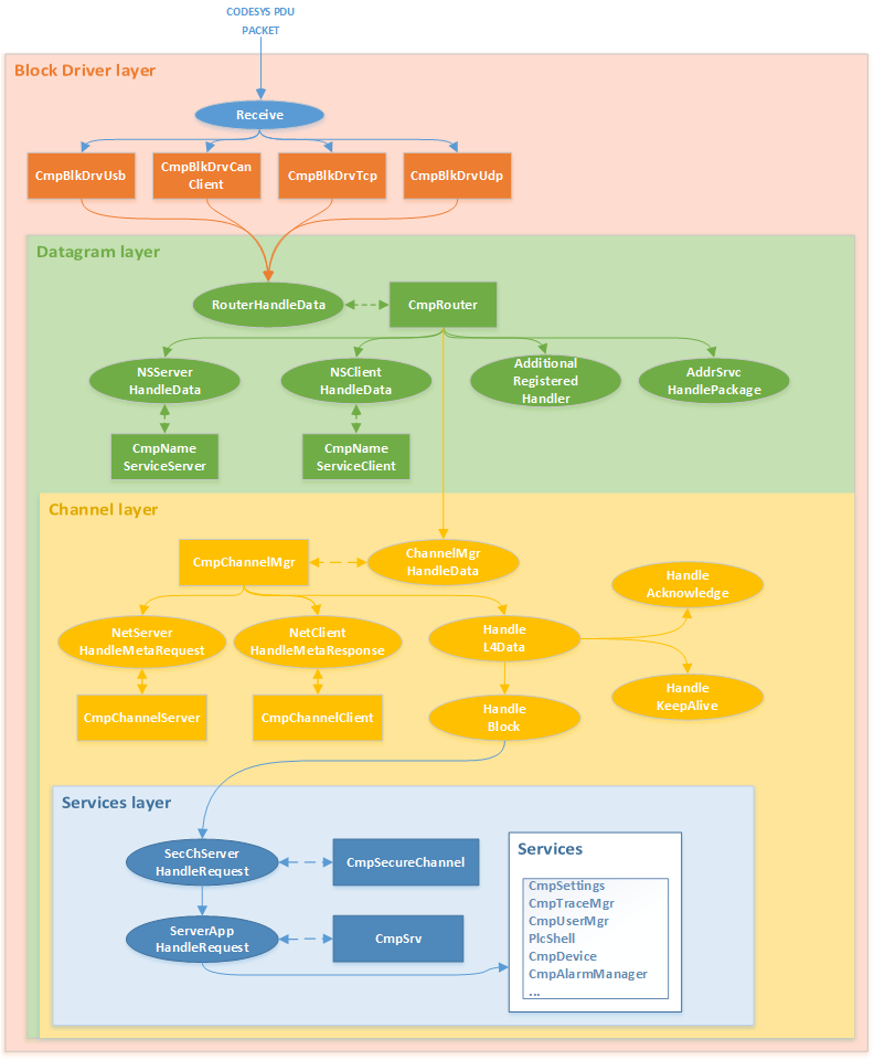
Schematic representation of how a CODESYS PDU packet is parsed by components
The cumulative operation of these components determines the capacity of the CODESYS PDU protocol stack.
This document examines each layer in the CODESYS PDU protocol stack.
Analysis of the protocol stack
Block Driver layer
All useful operation of CODESYS Runtime is the cumulative work of its components. The components can expand the capabilities of each other. This also works for components that parse the received packet generated over the PDU protocol.
The main task of components from the Block Drivers group is to create the capability to communicate over a physical or software interface. Any Block Drivers component is an “input point” for receiving an information packet and the point from which it is transmitted. Therefore, these components can add additional fields in the protocol prior to sending a packet.
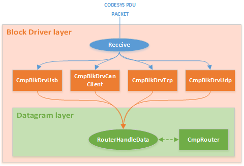
Schematic representation of how a CODESYS PDU packet is parsed by components at the Block Driver layer
For example, this is how the Block Driver CmpBlkDrvTcp component works. This component implements communication over the TCP protocol. In each message, CmpBlkDrvTcp adds two fields, each of which is a 4-byte number:
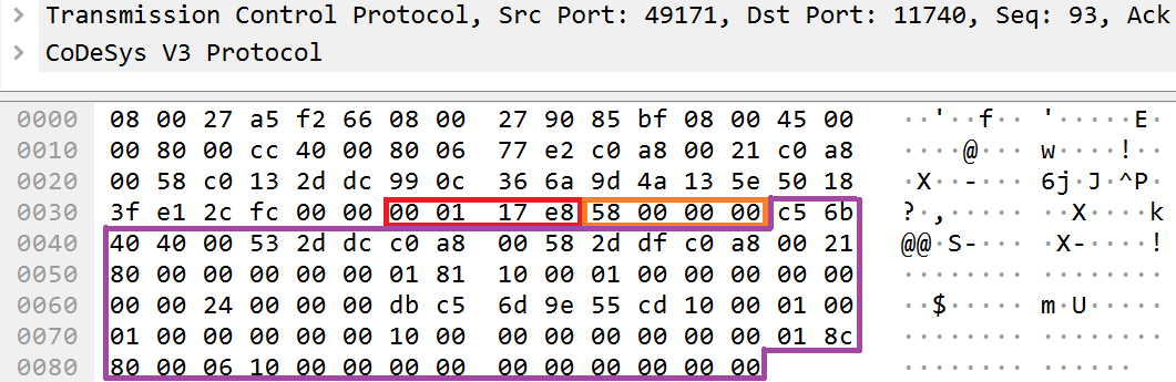

Example use of two additional fields at the Block Driver layer
- magic refers to the magic number. The constant number 0xe8170100 is inserted and verified by the CmpBlkDrvTcp component each time the component receives a network packet.
- length is the cumulative number of bytes in the packet, include the sizes of the magic and length fields (both fields have a size of 4 bytes each).
Below is a tracing of a call of the Receive() function, which belongs to the CmpBlkDrvTcp component. The Receive() function processes the magic and length fields.
Call trace:
	Removed at the vendor’s request
	Removed at the vendor’s request
	Removed at the vendor’s request
	Removed at the vendor’s request
	Removed at the vendor’s request

Pseudocode:
001: Removed at the vendor’s request
002: {
[...]
061:             Removed at the vendor’s request
[...]
068:             Removed at the vendor’s request
069:                             Removed at the vendor’s request
070:                             Removed at the vendor’s request
071:                             Removed at the vendor’s request
072:                             Removed at the vendor’s request
073:                             Removed at the vendor’s request
[...]
094:             Removed at the vendor’s request
095:             Removed at the vendor’s request
096:             {
099:               Removed at the vendor’s request
100:               {
[...]
101:               Removed at the vendor’s request
102:               {
[...]
144:               Removed at the vendor’s request
[...]
148:               Removed at the vendor’s request
149:                            Removed at the vendor’s request
150:                            Removed at the vendor’s request
151:                            Removed at the vendor’s request
152:                            Removed at the vendor’s request
153:                            Removed at the vendor’s request
[...]
179:                   Removed at the vendor’s request
180:                   Removed at the vendor’s request
[...]

196:       Removed at the vendor’s request
[...]
206: }
Decompiled pseudocode of the Receive function of the CmpBlkDrvTcp component
Receiving all data from the network for subsequent processing by the CmpBlkDrvTcp component occurs in two steps:
- At the first step, the component obtains the first 8 bytes (line 068) from the data received over the network through the SysSockRecv function, which was exported by the system component The maximum number of bytes that can be received is transmitted in the third argument of the SysSockRecv function. Then the first 4 bytes are compared with the magic constant (line 099). The second 4 bytes are compared with the number 520. The number 520 was obtained by adding the maximum possible size of a packet generated over the CODESYS PDU protocol (512 bytes) to the cumulative size of the magic and length fields (8 bytes).
- The remaining data is extracted at the second step. It is expected that the data size will be equal to the difference between the value of the length field and the cumulative size of the magic and length fields (line 144).
Then the CmpBlkDrvTcp component transfers management of the RouterHandleData function (line 196), which is registered by the CmpRouter component, to the Datagram layer.
Please bear in mind that the magic and length fields will be absent when communicating over the UDP protocol.

Example absence of additional fields at the Block Driver layer
The UdpReceiveBlock() function of the CmpBlkDrvUdp component is analogous to the Receive() function of the CmpBlkDrvTcp component.
Call trace:
	Removed at the vendor’s request
	Removed at the vendor’s request
	Removed at the vendor’s request
	Removed at the vendor’s request
	Removed at the vendor’s request
	Removed at the vendor’s request

Pseudocode:
001: Removed at the vendor’s request
002: {
019:
[...]
047:           Removed at the vendor’s request
[...]
055:     Removed at the vendor’s request
056:     {
[...]
064:           Removed at the vendor’s request
[...]
071:     }
072:     Removed at the vendor’s request
073:     {
[...]
080:         Removed at the vendor’s request
081:         Removed at the vendor’s request
083:     }
084:   }
[...]
111:     Removed at the vendor’s request
[...]
Decompiled pseudocode of the UdpReceiveBlock function of the CmpBlkDrvUdp component
The UdpReceiveBlock() function does not perform any verifications of the received data. Moreover, the CmpBlkDrvUdp component has another special feature. Namely, the UdpReceiveBlock() function listens for broadcast messages (line 047). If such data was not detected, the component attempts to count the data that was sent specifically to it (line 64). If data was received in one of these cases, the CmpBlDrvUdp component calls the RouterHandleData function for further processing (line 111).
Datagram layer
The Datagram layer is the next layer in the CODESYS PDU protocol stack. The main purpose of this layer is to route packets, detect nodes in the CODESYS network, and transmit data to the next layer. The main component in this layer is CmpRouter. The CmpNameServiceClient and CmpNameServiceServer components are auxiliary components.
Schematic representation of how a CODESYS PDU packet is parsed by components at the Datagram layer
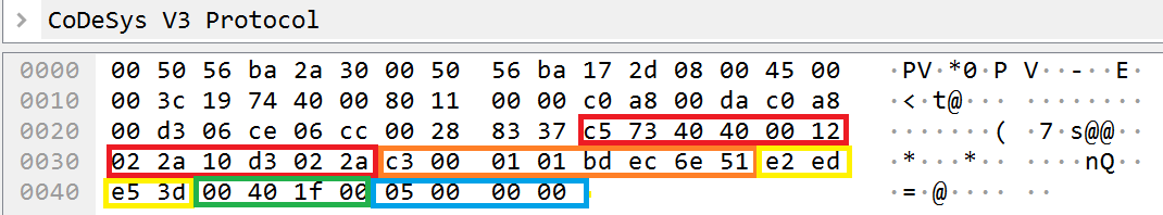
Components of the Block Drivers group are required to call the RouterHandleData function, which operates at the Datagram layer. In function call arguments, components transmit the received data.

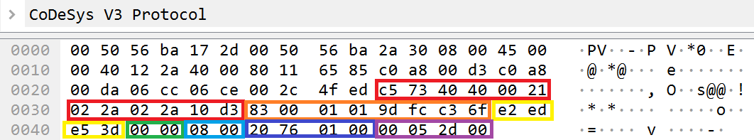
Utilized fields at the Datagram layer
In terms of traffic, this function processes the following fields and data:
- magic refers to the magic number of the packet generated over the CODESYS PDU protocol. The size of this field is one byte, and it is inserted by the CmpRouter
- hop_info refers to the bit structure, which consists of two fields: 5-bit hop_count field and 3-bit header_length field:
- The hop_count field is responsible for the possible number of transmissions of a packet received over the network. Each time one CODESYS network node receives a packet and redirects it to another CODESYS network node, it decrements the value of the hop_count If a node received a packet but is not its final recipient and the value of the hop_count field is equal to 0, the node will discard this packet. Essentially, this field protects a network that has CODESYS nodes from an endless forwarding of a packet.
- The header_length field indicates the number of bytes until the next field with the data size (lengths). When the value of the header_length field is added to its position in the packet, it is expected that the position on the lengths field will be obtained.
- packet_info refers to packet settings. This field also represents the bit structure.
- The first two bits are the priority It designates the priority of the processed packet. The following numerical values are used to designate priority: 0 – low, 1 – normal, 2 – high, 3 – emergency
- The following signal bit is used by the CmpRouter component as the returned packet processing status in which you can indicate errors.
- The type_address field indicates the type of transmitted address. This field is necessary so that the CmpRouter component can understand the contents of the sender and receiver There are two values for the type_address field: 0 – full address, 1 – relative address
- The last field length_data_block indicates the maximum size of data that can be accepted by a recipient.
- service_id refers to the ID of the service. Indicates which specific server must process the received data. CODESYS Runtime contains and identifies the following services:
- The service with an ID of 1 for a request and 2 for a response is the address service. This service is used to detect nodes that are “alive” in the network and to build an information network from these nodes. A node in this network serves as
a participant with CODESYS Runtime or CODESYS Development System running. - The service with an ID of 3 for a request and 4 for a response is the name service. This service is used to receive information about a node.
- The service with an ID of 64 (0x40) for both a request and response is the channel service. This service is used for querying the server and the communication channel manager.
- The service with an ID of 1 for a request and 2 for a response is the address service. This service is used to detect nodes that are “alive” in the network and to build an information network from these nodes. A node in this network serves as
- message_id refers to the ID of the message. This value is indicated by the sender and is used to identify the message. Normally CmpRouter sends a 4-bit value of the current time as the message ID. This provides for a unique message ID.
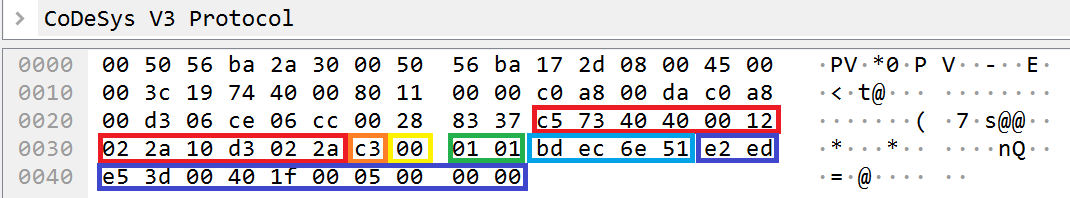
- lengths refers to the sizes of the receiver and sender The lengths field is a bit structure in which the most significant 4 bits contain a value corresponding to half of the number of bytes in the receiver field, while the least significant 4 bits contain a value corresponding to half of the number of bytes in the sender field. In other words, the number of bytes in the receiver field and in the sender field will be two times more than those specified in the lengths field. For example, the value of the most significant 4 bits of the lengths (0x53) field is equal to 5 for the examined packet. This means that the total number of bytes for the receiver field will be 10.
- sender refers to the address for which the message is intended.
- receiver refers to the address to which the response to the message must be sent.
- The padding field is added to the end of the packet. This field is optional.
The sender and receiver fields have their own data format that depends on the utilized Block Driver component. For example, CmpBlkDrvTcp expects the full network address of the node and number of the network port in these fields. In other words, the bytes of the receiver field (2ddcc0a80058) actually contain port 11740 (2ddc) and recipient address 192.168.0.88 (c0a80058).
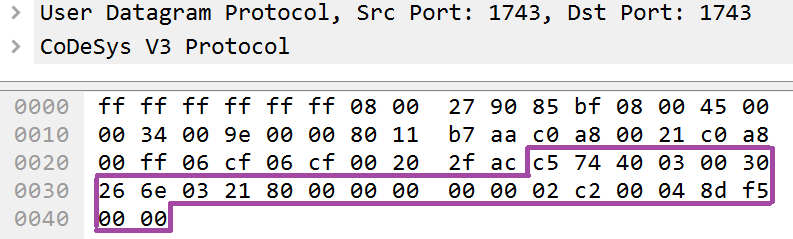
CmpBlkDrvUdp uses a different format. It uses a relative address instead of a full address, and it uses one byte instead of two bytes for the port value. This byte for the port indicates the port index. CmpBlkDrvUdp identifies four port indexes: 0, 1, 2, 3. Each index corresponds to one UDP port: 0 – 1740, 1 – 1741, 2 – 1742, 3 – 1743. The relative network address is the last byte in numerical format of the physical address.

Example contents of the Sender and Receiver fields when using the CmpBlkDrvUdp component
Therefore, the bytes value of the sender field (0058) will contain the port 1740 (the value of the port_index field is equal to 0x0) and the address 192.168.0.88 (0x58 is the last byte of the address, while the first three bytes are extracted from the interface address). The recipient will await a response at port 1743 (the value of the port_index field is equal to 0x3) and at the address 192.168.0.33 (0x21).
The purpose and format of all other data in the packet depends on the service (service_id) for which this packet is intended. If this ID is equal to 1, 2, 3 or 4, the handler remains the CmpRouter component or its auxiliary components CmpNameServiceClient and CmpNameServiceServer. If the ID is equal to 64 (0x40), all other data is transmitted to the CmpChannelManager component.
Based on the sender field, the CmpRouter component determines if the packet is intended for itself or if it needs to be forwarded to another node. In the first case, the CmpRouter component first decrements the value of hop_count in the packet, then sends it as is to the node specified in the sender field. In the second case, the CmpRouter component processes the packet and returns the result to the address specified in the receiver field. A packet that was intended for the node is processed by the HandleLocally function.
Call trace:
	Removed at the vendor’s request
	Removed at the vendor’s request
	Removed at the vendor’s request
	Removed at the vendor’s request
	Removed at the vendor’s request
	Removed at the vendor’s request
	Removed at the vendor’s request
	Removed at the vendor’s request

Pseudocode:
001: Removed at the vendor’s request
002: {
[...]
044:   Removed at the vendor’s request
045:   Removed at the vendor’s request
046:   {
[...]
051:     Removed at the vendor’s request
[...]
060:   }
061:   Removed at the vendor’s request
062:   {
063:     Removed at the vendor’s request
064:     {
[...]
069:       Removed at the vendor’s request
[...]
078:     }
079:     Removed at the vendor’s request
080:     {
[...]
086:       Removed at the vendor’s request
[...]
096:       Removed at the vendor’s request
097:     }
098:   }
099:   Removed at the vendor’s request
100:   {
101:     Removed at the vendor’s request
102:       Removed at the vendor’s request
103:     Removed at the vendor’s request
111:     [...]
119:     Removed at the vendor’s request
120:   }
121:   Removed at the vendor’s request
122:   {
123:     Removed at the vendor’s request
124:     {
125:       Removed at the vendor’s request
126:       Removed at the vendor’s request
127:         Removed at the vendor’s request
[...]
142:     }
143:   }
144:   Removed at the vendor’s request
145: }
Decompiled pseudocode of the HandleLocally function of the CmpRouter component
The HandleLocally function uses the value of the service_id field to determine which specific handler must be queried:
- For a value that is equal to 1 or 2: the AddrSrvcHandlePackage function (line 103). This is a handler of the address service.
- For a value that is equal to 3: the NSServerHandleData function (line 51). This is the handler of the name service, which processes incoming requests. In other words, it operates as a server.
- For a value that is equal to 4: the NSClientHandleData function (line 69). This is a handler of the name service, which processes the results of completed requests. In other words, it operates as a client.
- For a value that is equal to 0x40: the ChannelMgrHandleData function (line 86). This is a handler of the channel service.
If a suitable handler was not found for the received service_id, a search is performed among the additional handlers registered by the RouterRegisterProtocolHandler function. If one is found, it is queried (lines 125:127).
01: Removed at the vendor’s request
02: {
[...]
14:   Removed at the vendor’s request
15:   {
16:     Removed at the vendor’s request
17:     {
18:       Removed at the vendor’s request
19:       {
20:         Removed at the vendor’s request
21:       }
22:       Removed at the vendor’s request
23:       {
24:         Removed at the vendor’s request
25:         Removed at the vendor’s request
26:         Removed at the vendor’s request
[...]
39:   Removed at the vendor’s request
40: }
Decompiled pseudocode of the RouterRegisterProtocolHandler function
The RouterRegisterProtocolHandler function takes the service_id and handler as arguments (line 1). This function does not let you register the handler (line 16) for the following IDs: 1, 2, 3, 4 and 64 (0x40). If a handler is not set for a specific ID (line 18), the handler will be added to the global dictionary of handlers (s_protocolHandlers), where the key for the handler is the first argument of service_id (line 24).
Next we will examine handlers of CODESYS Runtime system services, namely the handlers of the address service and handlers of the name service.
The handler of the channel service is examined in the chapter titled “Channel layer“.
Address service
The handler of the address service uses the service_id to identify possible commands: the “request” command with service_id 1 and the “response” command with service_id 2. The AddrSrvcHandlePackage function is the handler.
Call trace:
	Removed at the vendor’s request
	Removed at the vendor’s request
	Removed at the vendor’s request
	Removed at the vendor’s request
	Removed at the vendor’s request
	Removed at the vendor’s request
	Removed at the vendor’s request
	Removed at the vendor’s request
	Removed at the vendor’s request

Pseudocode
01: Removed at the vendor’s request
02: {
[...]
23:   Removed at the vendor’s request
24:   {
25:     Removed at the vendor’s request
26:       Removed at the vendor’s request
27:   }
28:   Removed at the vendor’s request
29:   {
30:     Removed at the vendor’s request
31:     Removed at the vendor’s request
32:     {
33:       Removed at the vendor’s request
34:       {
[...]
75:             Removed at the vendor’s request
76:         }
77:       }
78:     }
[...]
98: }
Decompiled pseudocode of the AddrSrvcHandlePackage function
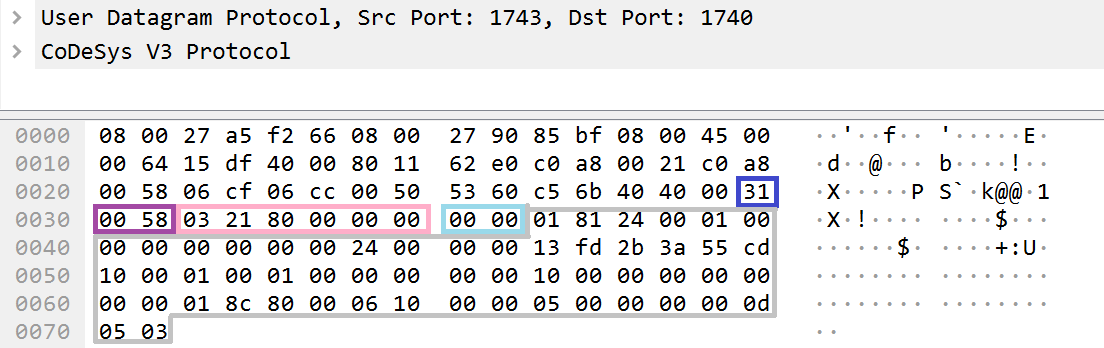
The “request” command with an ID of 1 (line 23) is sent by a CODESYS network node to notify the other nodes about its existence. This request can be continually monitored in the traffic over a broadcast address: it is sent at the same frequency by all CODESYS network nodes to a broadcast address.
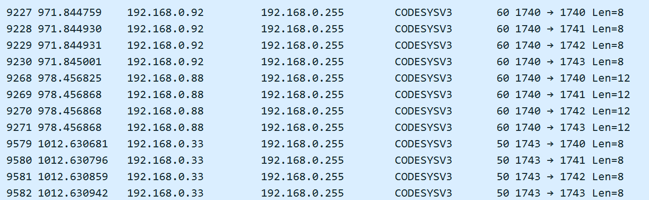
Broadcast notifications of CODESYS network nodes
If there is a parent node among the CODESYS network nodes, it learns about the existence of the node that sent the request. This same request can be sent by the parent node. If such a request is received by child objects, they notify the parent node about their existence. Additional fields are not used for this request.
The “response” command with an ID of 2 (line 28) is usually sent by a parent node. This command is used to build a CODESYS information network. It uses the following fields:

- version_major is a field that is used to designate the version of the CODESYS information network that will be generated. For the CODESYS PDU protocol, the value of version_major is always equal to 1 (line 75 of the decompiled pseudocode of the AddrSrvcHandlePackage function).
- version_minor is the field indicating the utilized version of the command. It determines the additional fields in the command and in the response. For example, if the field has a positive value, the parent_subnet_params field will be used in the packet.
- address_len indicates the number of bytes of the parent_address field that needs to be processed. The total number of bytes is multiplied by two.
- address refers to the address of the parent node.
- subnet_id refers to the ID of the generated subnet.
- subnet_params and parent_subnet_params are the settings of the current subnet and the subnet of the parent node.
The CODESYS network node that receives such a message sets the source of this message as the parent node (provided that no parent node was previously specified).
Name service
Messages that are intended for the name service are processed by the auxiliary components CmpNameServiceClient and CmpNameServiceServer. Messages of the name service are also divided into a “request” command and “response” command. Incoming “requests” from other nodes are processed by the CmpNameServiceServer component. Requests that were sent by the CODESYS Runtime node are processed as “responses” by the CmpNameServiceClient component.
The common header of name service messages (name_service_header) uses the following fields:

- subcmd refers to the ID of the command that the name service needs to execute.
- version refers to the command version number. This field determines the availability of additional fields in the message_data field that are typical for the specified version of the command.
- message_id refers to the ID of the message. This value is returned in a response. A numerical identifier of the current time is used to create the value of this field.
- message_data refers to command fields whose format is determined by the command (subcmd).
The CmpNameServiceServer component exports the NSServerHandleData function. The NSServerHandleData function serves as the handler of requests sent to the name service from other nodes.
Call trace:
	Removed at the vendor’s request
	Removed at the vendor’s request
	Removed at the vendor’s request
	Removed at the vendor’s request
	Removed at the vendor’s request
	Removed at the vendor’s request
	Removed at the vendor’s request
	Removed at the vendor’s request
	Removed at the vendor’s request

Pseudocode:
01: Removed at the vendor’s request
02: {
[...]
09:   Removed at the vendor’s request
10:     Removed at the vendor’s request
11:   Removed at the vendor’s request
12:     Removed at the vendor’s request
13:   Removed at the vendor’s request
14:   Removed at the vendor’s request
15:   {
[...]
18:     Removed at the vendor’s request
19:   }
20:   Removed at the vendor’s request
21:   {
[...]
24:     Removed at the vendor’s request
25:   }
26:   Removed at the vendor’s request
27:   {
28:     Removed at the vendor’s request
29:   }
30:   Removed at the vendor’s request
31: }
Decompiled pseudocode of the NSServerHandleData function of the CmpNameServiceServer component
The NsServerHandleData handler determines the two possible IDs of the subcmd field, and queries the corresponding auxiliary handler for each of them:
- For the ID 0xc202 (line 20), this is the HandleResolveAddrReq handler (line 18). This is a request to receive information about a node. A response to this request uses the value of service_id 4 and will be processed by the NsClientHandleData
- For the ID 0xc201 (line 14), this is the HandleResolveNameReq handler (line 18). This request is analogous to a request with the ID 0xc202, with the only difference being that the node name is transmitted in the body of the request. If the transmitted node name does not match the name of the node that received the request, the node ignores the request. A response to this request uses the value of service_id 4 and will be processed by the NsClientHandleData
The CmpNameServiceClient component exports the NSClientHandleData function that serves as the handler of responses to name service requests received from nodes. The response to the request uses the common message header (name_service_header). Depending on the value specified in the version field, the response may differ. For a version field that is equal to 0x103, the response will contain the following fields:

- max_channels refers to the number of simultaneously supported communication channels. This number is regulated by the settings of the CmpChannelMgr This same communication channel is used at the Channel layer of the CODESYS PDU protocol stack.
- byte_order indicates the byte order used in the protocol. As mentioned earlier, CODESYS PDU uses the little endian byte order by default. However, the byte order can be changed. A value of the byte_order field equal to 1 indicates the use of little endian byte order.
- Unknown means that we were unable to determine the purpose of the field during our research.
- node_name_length refers to the size of the node_name
- device_name_length refers to the size of the device_name
- vendor_name_length refers to the size of the vendor_name
- target_type refers to the type of device.
- target_id refers to the device ID.
- target_version refers to the version of the device.
- node_name refers to the network name of the device.
- device_name refers to the name of the device.
- vendor_name refers to the name of the organization that developed the device or implemented CODESYS Runtime into the device.
If the value 0x400 was indicated in the version field of the request, the response will contain the following fields: address of the parent node, license number, and type of Block Driver component.
Channel layer
The channel layer is the next layer in the CODESYS PDU protocol stack.
Schematic representation of how a CODESYS PDU packet is parsed by components at the Channel layer
A channel is a mechanism of communication between nodes of a CODESYS network that guarantees synchronization of communication, verification of the transmitted data integrity, notification of message delivery, and transmission of a large amount of data.
The main component at this layer is the CmpChannelMgr component (Component Channel Manager). This component is the communication channel manager. It tracks synchronization of communication between nodes and the integrity of received data, or transfers management to the channel server (the CmpChannelServer component) or a client of communication channels (the CmpChannelClient component).
The CmpChannelServer component is a channel server. It is responsible for the following:
- Creating an accumulation buffer for received and sent messages
- Creating and closing communication channels
- Delivering information about a communication channel
- Closing channels whose time to live expired or that haven’t been accessed for a long time
The CmpChannelClient component is a client of channels. It generates the necessary requests and handles the processing of responses from the channel server.
The CmpChannelMgr component exports the ChannelMgrHandleData function that is queried by the CmpRouter component if the value of the service_id field is equal to 0x40 at the Datagram layer.
Call trace:
	Removed at the vendor’s request
	Removed at the vendor’s request
	Removed at the vendor’s request
	Removed at the vendor’s request
	Removed at the vendor’s request
	Removed at the vendor’s request
	Removed at the vendor’s request
	Removed at the vendor’s request

Pseudocode:
001: Removed at the vendor’s request
[...]
079:     Removed at the vendor’s request
080:     {
[...]
086:       Removed at the vendor’s request
[...]
096:       Removed at the vendor’s request
097:     }
[...]
Locations for transferring management of the ChannelMgrHandleData function
A common header (channel_common_header) is used for the channel layer. It contains the following fields:

- The package_type field determines the type of packet. If the most significant bit is set in the value of this field, the packet is a command for the channel server. If the most significant bit is absent, the packet is intended for the channel manager.
- The flags field has a varying purpose depending on the package_type field.
- The packet_data field contains the other packet data that is determined by the packet_type field.
The ChannelMgrHandleData function exported by the CmpChannelMgr component is the handler at the Channel layer. Operations of this function can be divided into three categories: operations with the channel server, operations with the channel client, and operations with the channel manager.
Call trace:
	Removed at the vendor’s request
	Removed at the vendor’s request
	Removed at the vendor’s request
	Removed at the vendor’s request
	Removed at the vendor’s request
	Removed at the vendor’s request
	Removed at the vendor’s request
	Removed at the vendor’s request
	Removed at the vendor’s request

Pseudocode:
01: Removed at the vendor’s request
02: {
[...]
20:       Removed at the vendor’s request
21:       {
22:         Removed at the vendor’s request
23:         {
[...]
27:           Removed at the vendor’s request
28:         }
29:       }
30:       Removed at the vendor’s request
31:       {
[...]
35:         Removed at the vendor’s request
36:       }
37:     }
 [...]
43:       Removed at the vendor’s request
44:     }
45:     Removed at the vendor’s request
[...]
48: }
Fragment of the decompiled pseudocode of the ChannelMgrHandleData function of the CmpChannelMgr component
Operations with the channel server occur in the NetServerHandleMetaRequest handler.
A response from the channel server is processed by the channel client in the NetClientHandleMetaResponse handler (line 35) and (line 27).
Operations with the channel manager occur in the HandleL4Data function (line 43).
Commands for the communication channel server
We first examine the group of commands for working directly with the communication channel server. This group contains commands for opening and closing the channel, and for receiving information about the communication channel server.
Call trace:
	Removed at the vendor’s request
	Removed at the vendor’s request
	Removed at the vendor’s request
	Removed at the vendor’s request
	Removed at the vendor’s request
	Removed at the vendor’s request
	Removed at the vendor’s request
	Removed at the vendor’s request
	Removed at the vendor’s request

Pseucode:
01: Removed at the vendor’s request
02: {
[...]
27:           Removed at the vendor’s request
[...]
35:         Removed at the vendor’s request
36:       }
[...]
48: }
Fragment of the decompiled pseudocode of the ChannelMgrHandleData function
The command handler for the communication channel server is the NetServerHandleMetaRequest function, and the command handler for a client is the NetClientHandleMetaResponse function. The first function processes incoming requests, which means it implements the server side. The second function processes responses to requests, which means it implements the client side. Both of these functions will be examined below.
Call trace:
	Removed at the vendor’s request
	Removed at the vendor’s request
	Removed at the vendor’s request
	Removed at the vendor’s request
	Removed at the vendor’s request
	Removed at the vendor’s request
	Removed at the vendor’s request
	Removed at the vendor’s request
	Removed at the vendor’s request

Pseudocode:
01: Removed at the vendor’s request
02: {
03:   Removed at the vendor’s request
04:
05:   Removed at the vendor’s request
06:     Removed at the vendor’s request
07:   Removed at the vendor’s request
08:   Removed at the vendor’s request
09:   {
10:     Removed at the vendor’s request
11:       Removed at the vendor’s request
12:       Removed at the vendor’s request
13:     Removed at the vendor’s request
14:       Removed at the vendor’s request
15:       Removed at the vendor’s request
16:     Removed at the vendor’s request
17:       Removed at the vendor’s request
18:       Removed at the vendor’s request
19:   }
20:   Removed at the vendor’s request
21: }
Fragment of the decompiled pseudocode of the NetServerHandleMetaRequest function
The NetServerHandleMetaRequest function (line 01) identifies three possible IDs of a command (command_id) to be processed:
- 0xC2 (line 16) for the GET_INFO The HandleInfoReq function (line 17) serves as the command handler.
- 0xC3 (line 10) for the OPEN_CHANNEL The HandleOpenChannelReq function (line 11) serves as the command handler.
- 0xC4 for the CLOSE_CHANNEL The HandleCloseChannelReq function (line 14) serves as the command handler.
Call trace:
	Removed at the vendor’s request
	Removed at the vendor’s request
	Removed at the vendor’s request
	Removed at the vendor’s request
	Removed at the vendor’s request
	Removed at the vendor’s request
	Removed at the vendor’s request
	Removed at the vendor’s request
	Removed at the vendor’s request
	Removed at the vendor’s request

Pseudocode:
23: Removed at the vendor’s request
24: {
25:   Removed at the vendor’s request
26:
27:   Removed at the vendor’s request
28:     Removed at the vendor’s request
29:   Removed at the vendor’s request
30:   Removed at the vendor’s request
31:   {
32:     Removed at the vendor’s request
33:   }
34:   Removed at the vendor’s request
35:   {
36:     Removed at the vendor’s request
37:   }
38:   Removed at the vendor’s request
39: }
Fragment of the decompiled pseudocode of the NetClientHandleMetaResponse function
The client function NetClientHandleMetaResponse (line 23) identifies only two possible commands for a client:
- 0xC3 (line 30) for the OPEN_CHANNEL The HandleOpenChannelResp function (line 32) serves as the command handler.
- 0xC4 (line 34) for the CLOSE_CHANNEL The HandleCloseChannelResp function (line 36) serves as the command handler.
A channel layer message that is intended for the server and client of a channel has its own header (channel_header). The following fields are used in the channel_header:

- The command_id field designates the ID of the command and indicates whether the message is a request or a response to a request. A set 7th bit indicates that the message is a response. The other first 6 bits designate the command ID. The following IDs of commands are available for the channel server:
- 0xc2 (GET_INFO) refers to an information command for obtaining the number of simultaneously supported channels on the node.
- 0xc3 (GET_CHANNEL) refers to a request to create a communication channel between nodes.
- 0xc4 (CLOSE_CHANNEL) refers to a request to close a communication channel between nodes.
- During our research, we did not detect the use of a value set in the flags field.
- The version field indicates the ID of the command version. Depending on this field, additional fields may be used in the body of the command message.
- The remaining data of a command is determined by the command (command_id).
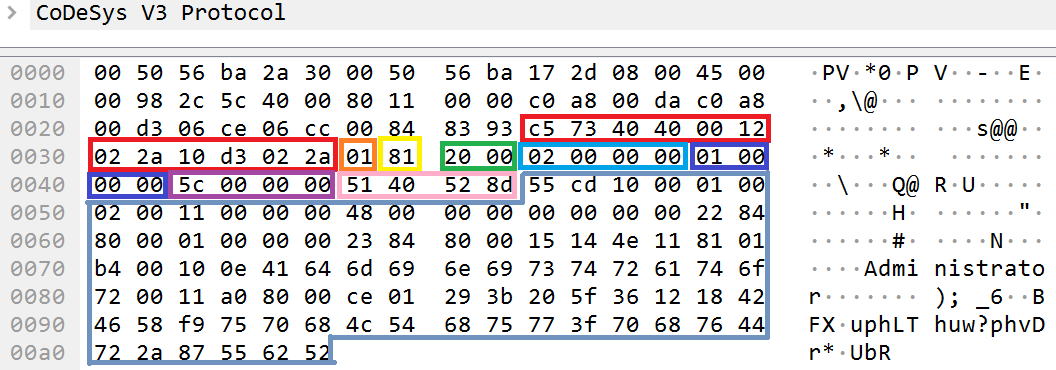
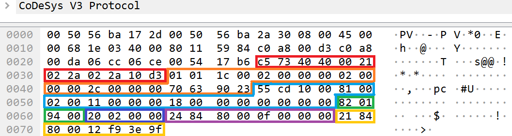
For example, for a request to open a communication channel, the server function NetServerHandleMetaRequest processes the following fields and data:

Utilized fields at the Channel layer
- command_id with the ID 0xc3 means that the message is a request to open a communication channel (GET_CHANNEL).
- The flags field will be ignored when the GET_CHANNEL command is processed.
- The version field determines the availability of additional fields in a message. For the current value, two additional fields will be used.
- checksum refers to the packet checksum. The CRC32 algorithm is used for the checksum.
- command_data is a field that is examined below.
The following fields and data is used for a GET_CHANNEL command request:
![]()
Utilized fields of a request with the GET_CHANNEL command
- The datagram_layer_fields field refers to fields of the Datagram layer.
- The channel_header field refers to the header of a command sent to the channel server.
- Message_id refers to the ID of the message. A 4-bit representation of the current time is normally used as the value of this field.
- Receiver_buffer_size refers to the maximum permissible amount of data that can be accumulated by the recipient in the communication channel.
In response to this request, the command_id field of the channel_header sets the 7th bit. The command_data fields in the response to the request will be as follows:

Utilized fields of a response to the GET_CHANNEL command
- The datagram_layer_fields field refers to fields of the Datagram layer.
- The channel_header field is the header of a command sent to a channel client.
- Message_id refers to the returned message ID. This value is equivalent to the value that was received in the request.
- Reason refers to the command processing status.
- Channel_id refers to the ID of the open communication channel.
- Receiver_buffer_size refers to the maximum permissible amount of data that can be accumulated by the recipient in the communication channel.
Other commands use their own set of fields in the command_data field. One exclusion is the GET_INFO command. To receive the result of this command, all you have to do is send a filled channel_header that specifies the ID of the GET_INFO command. The response will contain one field:

- The Max_channels field contains the maximum number of simultaneously supported communication channels.
A request to close a channel (CLOSE_CHANNEL) uses the following fields in command_data:

- channel_id refers to the ID of the channel that needs to be closed.
- reason refers to the reason for closing the channel.
The node that received this request does not return any response.
Commands for the communication channel manager
The second examined group of commands works directly with the communication channel manager. An open communication channel is required for querying any command from this group. This group contains commands for transferring data to the next layer, and notifications about its receipt and support for the created communication channel.
Commands for the communication channel manager use the common header (channel_manager_header) with the following fields:

- packet_type refers to the ID of the packet type. The following types of packets and their purposes are identified:
- BLK refers to the transfer of data for the next layer in the protocol stack.
- ACK refers to a notification about data receipt.
- KEEPALIVE refers to keeping a communication channel active.
- Flags are additional settings or indicators that are specific to the packet type (packet_type).
- packet_data refers to the specific data for the packet type (packet_type).
The HandleL4Data function processes all commands of the examined group.
Call trace:
	Removed at the vendor’s request
	Removed at the vendor’s request
	Removed at the vendor’s request
	Removed at the vendor’s request
	Removed at the vendor’s request
	Removed at the vendor’s request
	Removed at the vendor’s request
	Removed at the vendor’s request
	Removed at the vendor’s request
	Removed at the vendor’s request

Pseudocode:
01: Removed at the vendor’s request
02: {
[...]
17:
20:   Removed at the vendor’s request
21:   Removed at the vendor’s request
22:   Removed at the vendor’s request
23:   Removed at the vendor’s request
24:   {
25:     Removed at the vendor’s request // ACK
26:       Removed at the vendor’s request
27:       Removed at the vendor’s request
28:         Removed at the vendor’s request
29:       Removed at the vendor’s request
30:       Removed at the vendor’s request
31:     Removed at the vendor’s request // KEEPALIVE
32:       Removed at the vendor’s request
33:       Removed at the vendor’s request
34:     Removed at the vendor’s request // BLK
35:       Removed at the vendor’s request
36:       Removed at the vendor’s request
37:         Removed at the vendor’s request
38:       Removed at the vendor’s request
39:       Removed at the vendor’s request
[...]
43:   }
[...]
62:   Removed at the vendor’s request
63:   {
[...]
69:     Removed at the vendor’s request
72:     Removed at the vendor’s request
73:   }
74:   Removed at the vendor’s request
75:   {
81:     Removed at the vendor’s request
82:   }
[...]
94: } }
Fragment of the decompiled pseudocode of the HandleL4Data function
The HandleL4Data function (line 01) identifies three possible IDs of packet_type for processing BLK (0x1), ACK (0x2), KEEPALIVE (0x3).
Each packet type as specific type of data body. For instance, the BLK packet type uses the following fields in a message body:

Utilized fields for the BLK packet type at the Channel layer
- Packet_type refers to the BLK (0x1) packet type, which indicates data transfer.
- Flags refers to packet flags for the BLK packet type. The specified value 0x81 means the following:
- The node that received this packet serves as the server (most significant bit), and the data of the request is the first in the transmission (least significant bit).
- If the least significant bit is not set, the message contains a continuation of the data of the last packet. The least significant bit of this packet indicates that the packet is sending data to the next layer for the first time.
- Channel_id refers to the ID of the open channel used for data transfer.
- Blk_id refers to the ID of the current BLK message. This ID is incremented each time by the side that initiated the start of communication over the channel.
- Ack_id refers to the ID of the last ACK message. This ID is changed by the responding side each time. After receiving the last packet for data transfer to a service at the application layer, the responding side changes the value of this ID to
- Remaining_data_size refers to the size of the expected data contained by the remaining_data
- Checksum is the checksum of the data contained in the remaining_data The CRC32 algorithm is used to calculate the checksum.
If a BLK packet contained data whose size does not exceed the maximum size of a CODESYS PDU packet (512 bytes), the response will contain a modified value of the flags field in which the most significant bit will not be set, meaning that the recipient is now the client. The value of the ack_id field will be changed to the value of the blk_id field.
Despite the fact that the maximum size of a CODESYS PDU packet is 512 bytes, very large-sized data can be transmitted over the CODESYS PDU protocol. This is possible through the accumulation of incoming data on the receiving side. The receiving side understands that data needs to be accumulated due to the values in the flags field. The checksum and remaining_data_size fields indicate when the packet contains the last data for a command.
The ACK message type is used for notifying the sending side that a portion of the data was received and the next portion of data is anticipated. This message uses the following fields:

- Channel_id is the ID of the channel used to receive the BLK packet.
- Blk_id refers to the value of the Blk_id field from the BLK packet that was received by the receiving side.
The KEEPALIVE message type is used to keep the open communication channel active. If the channel manager is not receiving messages, it will soon close the channel. The message timeout before the channel is closed is regulated by the component settings.
The KEEPALIVE message type uses one field:

- Channel_id is the ID of the channel whose time needs to be extended.
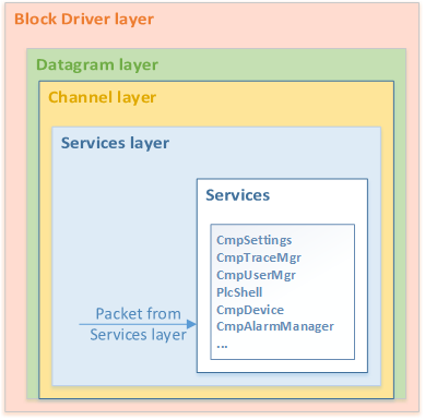
Services layer
The next layer in the CODESYS PDU protocol stack is the Services layer.
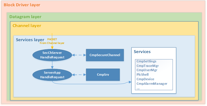
Schematic representation of how a CODESYS PDU packet is parsed by components at the Services layer
The Services layer represents a combination of several layers of the ISO/OSI model: session layer, presentation layer, and application layer. The main task of this layer is to query the requested service and transmit its operating settings. Additional tasks of the Services layer include encoding, decoding, encrypting, and decrypting data transmitted at this layer. Another additional task is support of sessionization on a device.
The latest implementations of CODESYS Runtime support data encryption at the Services layer. The CmpSecureChannel component encrypts and decrypts data at this layer. This occurs in the SecChServerHandleRequest function that is exported by it. If data was successfully decrypted or if it was not initially encrypted, it is transmitted to the ServerAppHandleRequest function that was exported by the CmpSrv component.
If there is no CmpSecureChannel component, the CmpChannelServer component independently transfers management to the ServerAppHandleRequest function.
The format of the message header (protocol_header) for an encrypted or unencrypted message is as follows:

- protocol_id refers to the ID of the utilized protocol. This ID indicates which protocol handler modified the data and which protocol should be used to transmit data to services. There are two system IDs of the protocol:
- HeaderTagProtocol with the ID 0xcd55. This protocol ID indicates that data of the protocol_data field contains tags.
- SecureProtocol with the ID 0x7557 refers to the protocol for secure data transfer. This ID indicates that data of the protocol_data field needs to be decrypted.
- Header_size refers to the size of the protocol_header. The value of this field does not contain the sizes of previous fields and the current field.
- service_group refers to the ID of the queried service. If the most significant bit is set in the ID, this means that the message is a response from a service. Based on the service ID, the following components are identified as a service:
- CmpAlarmManager – 0x18;
- CmpApp – 0x2;
- CmpAppBP – 0x12;
- CmpAppForce – 0x13;
- CmpCodeMeter – 0x1d;
- CmpCoreDump – 0x1f;
- CmpDevice – 0x1;
- CmpFileTransfer – 0x8;
- CmpIecVarAccess – 0x9;
- CmpIoMgr – 0xb;
- CmpLog – 0x5;
- CmpMonitor – 0x1b;
- CmpOpenSSL – 0x22;
- CmpSettings – 0x6;
- CmpTraceMgr – 0xf;
- CmpTraceMgr – 0xf;
- CmpUserMgr – 0xc;
- CmpVisuServer – 0x4;
- PlcShell – 0x11;
- SysEthernet – 0x7.
- service_id refers to the ID of the command. This ID determines what exactly the service must do.
- session_id refers to the ID of the session. It contains the value of the received session or empty session. This value is checked by protocol handlers and by most commands that require elevated user privileges.
- content_size refers to the size of data in the protocol_data field.
- additional_data refers to the field used for additional data.
- protocol_data refers to data generated over the utilized protocol (protocol_id).
If a message was encrypted by the SecureProtocol, almost all fields of the protocol_header will contain zero bytes. An exception would be the header_size and content_size fields, which operate normally, and the protocol_data field that contains an encrypted protocol_header. After the protocol_data field is decrypted, the decrypted protocol_header will be processed by the HeaderTagProcol protocol handler.
If the message was not encrypted and the HeaderTagProcol protocol was used, the protocol_data field will contain tags.
A user can register their handler for protocol_id using the ServerRegisterProtocolHandler function that is exported by the CmpSrv component:
01: Removed at the vendor’s request
02: {
[...]
06:
07:   Removed at the vendor’s request
08:   Removed at the vendor’s request
09:     Removed at the vendor’s request
10:   Removed at the vendor’s request
11:   {
12:     Removed at the vendor’s request
13:       Removed at the vendor’s request
14:   }
15:   Removed at the vendor’s request
16:   {
17:     Removed at the vendor’s request
18:     {
19:       Removed at the vendor’s request
20:       Removed at the vendor’s request
21:     }
22:   }
23:   Removed at the vendor’s request
24:     Removed at the vendor’s request
25:   Removed at the vendor’s request
26:   Removed at the vendor’s request
27:   Removed at the vendor’s request
28:     ++Removed at the vendor’s request
29:   Removed at the vendor’s request
30: }
Decompiled pseudocode of the ServerRegisterProtocolHandler function
The ServerRegisterProtocolHandler function is quite simple, and its algorithm consists of the following:
- At lines 10 through 12, the function compares each of the registered handlers for the protocol_id field with the handler that is expected to be registered. If this handler is detected among the registered handlers, the function returns the corresponding status (line 13).
- Then it attempts to find an unoccupied cell for registering the handler (lines 15:21).
- It registers the new handler in an unoccupied cell (line 25:26).
For the service_id field, one component can register only one handler simultaneously. To register a handler for service_id, the ServerRegisterServiceHandler function must be queried. Its algorithm is analogous to the algorithm of the ServerRegisterProtocolHandler function. Therefore, we will not examine it here.
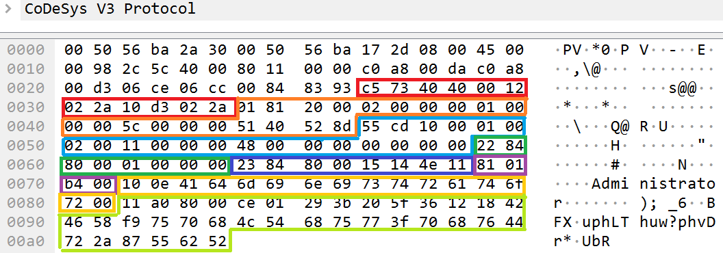
For example, for a non-encrypted request to complete authentication, the ServerAppHandleRequest function processes a packet as follows:
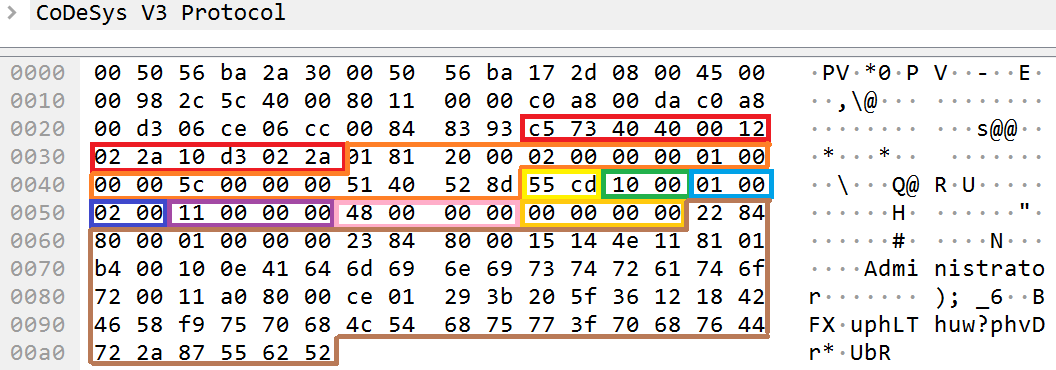

Example contents of fields at the Services layer
- Protocol_id contains the ID 0xcd55. This means that the HeaderTagProtocol protocol was used: data of the protocol_data field is not encrypted, and the service_group and service_id fields contain the values of the requested service.
- Header_size contains the value 0x10. This means that the size of the utilized header (protocol_header) is 16 (0x10) bytes.
- Service_group indicates the ID of the service that was registered by the CmpDevice component.
- Service_id indicates the ID of the requested command for the service. The value 2 indicates that the service registered by the CmpDevice component needs to execute the AUTH command.
- Protocol_data_size indicates that the data size of the protocol_data field is 72 (0x48) bytes.
- The additional_data field was not used.
Tags
The last examined layer in the CODESYS PDU protocol stack is tags.
Schematic representation of how a CODESYS PDU packet is parsed by components at the Services layer
Tags refer to the interface for transmitting settings for services. The service on the client side knows how data needs to be formulated so that the service on the server side correctly receives the settings of this data.
Types of tags
Tags are transmitted in the protocol_data field of the protocol_header. They can be of two types: a data tag or a parent tag.
Both types of tags have an identical structure, but use different sizes for the first two elements of the structure of fields:

- tag_id refers to the tag ID. The IDs of a parent tag and data tag are distinguished by the value of the most significant bit. If the value of the most significant bit is set, this means that the tag is a parent tag and all other data is typical for a parent tag. Otherwise the tag is a data tag, and its data contains the final settings for the service.
- tag_size refers to the size of the data. This field determines the amount of data in the tag_data In addition, the value of the most significant bit of the tag_size field determines the availability of the additional field additional_data: if the value of the most significant bit is set, the additional_data field is available.
- additional_data is an additional field. It has a dynamic size, which cannot be larger than 10 bytes. The end of this field is determined by a zero byte.
- tag_data refers to data of the parent tag or data of the data tag.
Data extracted by a service from a data tag is converted into a specific type of data. For example, a tag containing 4 bytes in the tag_data field may be converted to one of the numerical data types by the service. The variable type is not transmitted in the tag structure. However, may times it was observed that CODESYS Runtime services transmit a group of tags from which one tag may contain a value, the second tag – type ID, and the third – size. These bundles of tags are usually combined under one parent tag.
A parent tag is used for linking several types into one logical element. An example of this type of linking was presented above. Another example is the linking of tags with a user name and password that are used for authentication. A data tag containing a user name and a data tag containing a password may be combined into one parent tag.
Processing tags
Let’s examine how a specific service handler extracts settings from received tags based on an example packet containing tags for user authentication. In this case, tags will be analyzed as follows:

Example parsing of the contents of the protocol_data field for tags in an authentication request
There is a protocol_data field inside the services_layer_fields header. If this field is broken down into tags, it has 4 data tags and 1 parent tag.
The hierarchy of tags will be as follows:
- Data_tag_1
- Data_tag_2
- Parent_tag_1
- Data_tag_3
- Data_tag_4
Data_tag_1 and Data_tag_2 are at the same level as Parent_tag_1.
Data_tag_3 and Data_tag_4 are within the parent tag.
Interaction with tags occurs through the utilization of a multitude of API functions, which include functions for interaction with incoming tags with the BTagReader (Binary Tag Reader) prefix, and functions for interaction with outgoing tags with the BtagWriter (Binary Tag Writer) prefix.
Main API functions for interaction with tags:
For incoming tags
- BTagReaderInit refers to initialization of the structure for reading received data. The data read structure stores the following elements: data, current position in the data, possible end position of data, and data size. In most cases, all functions for interaction with incoming tags use only the pointer to the current position in data. This is how it moves through tags in pure data.
- BTagReaderGetTagId refers to getting the tag ID.
- BTagReaderGetContent refers to getting the tag data.
- BTagReaderMoveNext refers to moving to the next tag.
- BTagReaderSkipContent refers to moving to the end of data of the current tag.
For outgoing tags
- BTagWriterInit refers to initialization of the structure for writing outgoing data. The data write structure stores the following elements: initially received data, pointer to the end of data, and current size of data. All functions for interaction with outgoing tags change all elements of the structure.
- BTagWriterStartTag refers to opening a new tag for outgoing data. Opening a tag must be accompanied by a query of the function for closing the tag – BTagWriterEndTag.
- BTagWriterAppendBlob refers to adding data for a created tag.
- BTagWriterEndTag refers to closing the created data tag.
- BTagWriterFinish refers to finishing writing tags as outgoing data. Essentially, this function verifies that all added tags have a valid structure and were closed by the BTagWriterEndTag
The packet has a services_layer_fields header in which the value of the service_group field is equal to 1. This ID is registered by the CmpDevice component. During its initialization, the component registers the DeviceServiceHandler function as a service by settings its ID equal to 1:
Call trace:
	Removed at the vendor’s request

Pseudocode:
1: Removed at the vendor’s request
2: {
3:   Removed at the vendor’s request
4: }
Decompiled pseudocode of the DeviceSrvInitComm function of the CmpSrv component
In this packet, the command specified in the command ID field (service_id) is equal to 2. The DeviceServiceHandler function identifies 9 commands that include a command with the ID 2 (line 254):
001: Removed at the vendor’s request
002: {
[...]
133:   Removed at the vendor’s request
134:   {
135:     Removed at the vendor’s request
[...]
254:     Removed at the vendor’s request
[...]
399:     Removed at the vendor’s request
[...]
411:     Removed at the vendor’s request
[...]
473:     Removed at the vendor’s request
[...]
548:     Removed at the vendor’s request
[...]
611:     Removed at the vendor’s request
[...]
624:     Removed at the vendor’s request
[...]
695:     Removed at the vendor’s request
[...]
763: }
Fragment of the decompiled pseudocode of the DeviceServiceHandler function
The DeviceServiceHandler function executes a command with the ID 2 in three steps:
- Extracts the settings and sets the local values.
- Executes commands with the local values and the received settings.
- Returns the result of command execution.
001: Removed at the vendor’s request
002: {
[...]
129:   Removed at the vendor’s request
130:   Removed at the vendor’s request
131:   Removed at the vendor’s request
132:   Removed at the vendor’s request
133:   Removed at the vendor’s request
134:   {
[...]
254:     Removed at the vendor’s request
[...]
266:       Removed at the vendor’s request
267:       Removed at the vendor’s request
268:       {
269:         Removed at the vendor’s request
270:         Removed at the vendor’s request
271:         {
272:           Removed at the vendor’s request
273:             Removed at the vendor’s request
274:             Removed at the vendor’s request
275:           Removed at the vendor’s request
276:             Removed at the vendor’s request
277:             Removed at the vendor’s request
278:             {
279:               Removed at the vendor’s request
280:               Removed at the vendor’s request
281:               {
282:                 Removed at the vendor’s request
283:               }
284:               Removed at the vendor’s request
285:               {
286:                 Removed at the vendor’s request
287:                 Removed at the vendor’s request
288:               }
289:               Removed at the vendor’s request
290:               {
291:                 Removed at the vendor’s request
292:               }
293:               Removed at the vendor’s request
294:               Removed at the vendor’s request
295:               Removed at the vendor’s request
296:             }
297:             Removed at the vendor’s request
298:           Removed at the vendor’s request
299:             Removed at the vendor’s request
300:             Removed at the vendor’s request
301:           Removed at the vendor’s request
302:             Removed at the vendor’s request
303:             Removed at the vendor’s request
304:         }
305:         Removed at the vendor’s request
306:         Removed at the vendor’s request
307:         Removed at the vendor’s request
308:       }
[...]
315:       Removed at the vendor’s request
316:       {
317:         Removed at the vendor’s request
318:         Removed at the vendor’s request
[...]
327:       }
330:       Removed at the vendor’s request
331:       Removed at the vendor’s request
332:       {
333:         Removed at the vendor’s request
334:       }
335:       Removed at the vendor’s request
336:       {
337:         Removed at the vendor’s request
338:         Removed at the vendor’s request
339:         {
[...]
341:           Removed at the vendor’s request
342:           Removed at the vendor’s request
343:           Removed at the vendor’s request
344:           Removed at the vendor’s request
345:           Removed at the vendor’s request
346:           Removed at the vendor’s request
347:           Removed at the vendor’s request
348:           Removed at the vendor’s request
349:         }
[...]
357:         Removed at the vendor’s request
[...]
365:         Removed at the vendor’s request
366:       }
367:       Removed at the vendor’s request
[...]
376:       Removed at the vendor’s request
377:       Removed at the vendor’s request
378:       Removed at the vendor’s request
379:       Removed at the vendor’s request
380:       Removed at the vendor’s request
[...]
389:       Removed at the vendor’s request
390:       Removed at the vendor’s request
391:       Removed at the vendor’s request
392:       Removed at the vendor’s request
393:       Removed at the vendor’s request
394:       Removed at the vendor’s request
395:       Removed at the vendor’s request
396:       Removed at the vendor’s request
397:       Removed at the vendor’s request
398:       Removed at the vendor’s request
[...]
761:   }
762:   Removed at the vendor’s request
763: }
Fragment of the decompiled pseudocode of the DeviceServiceHandler function
The algorithm for a command with the ID 2 for each step is as follows:
Settings extraction step
- Line 131 involves initialization of the structure for writing outgoing data (writer), will be used at the results return step. Line 132 involves initialization of the structure for reading incoming data (reader), which is used at the current step.
- There is an attempt to recognize tags within incoming data (line 266). If successful, the tag ID is extracted from the first tag (line 269).
- Depending on the tag ID received at the previous step, tag data is written to the corresponding variables. For the ID 0x23 (line 272), data is written to the pulChallenge variable (line 273). For the ID 0x22 (line 298), data is written to the pulCrypeType variable (line 299).If a tag ID is equal to 0x81 (line 275), the tag is a parent tag and it is searched for data tags (line 279) with the ID of 16 (line 280). Data from the found tags is written to the user_name variable (line 282).From the found tag with the ID 17 (line 284), data is written to the encrypted_password variable (line 286).
- Line 315 involves verifying that the variables necessary for executing the command have been filled with data from tags.
Command execution step
- The received encrypted_password, pulCrypeType and pulChallenge variables are used in the function for decrypting the UserMgrDecryptPassword (line 318). The decrypted password will be written to the decrypted_password
- The user_name variable will be used in the function for checking the existence of FindUser This function searches for an entry regarding users in the database.
- If an entry is found about a user that has a name from the user_name variable, the user’s password is checked to see if it matches the decrypted password that was saved to the decrypted_password
- If the decrypted password matches the password from the database, the current user is checked for permissions to a “Device” object (line 357).
- If the user has permissions to a “Device” object, the generated session ID (ulSessionId variable) is assigned to the current user (line 365) and to the utilized communication channel (line 367).
Results return step
- A tag with the ID 0x82 (line 376) is opened for outgoing data. This tag is a parent tag, and within it the tags with an ID of 0x20 (opening at line 377 and closing at line 379), 0x24 (opening at line 389 and closing at line 391) and 0x21 (opening at line 392 and closing at line 394) are sequentially opened and closed.
- The following values are written to data tags: with the ID 0x20 – value of the command execution status (line 378); with the ID 0x24 – value of device settings (line 390); with the ID 0x21 – value of the generated session (line 393).
- At line 395, the parent tag with the ID 0x82 is closed and writing of outgoing data is finished (line 396).
If a user entry is not found, permissions are insufficient, passwords do not match, or data is incorrect, the corresponding response is generated at the results return step.
In response to a request for CODESYS Runtime authentication with the correct user authentication data, the following packet is returned:

Example parsing of the contents of the protocol_data field for tags in a response to an authentication request
Consequently, we can unequivocally determine which tags with which IDs will be used to transmit specific settings for services. The main settings in this response will be contained in a tag with the ID 0x21. This tag will contain the session ID that will later be used as the value of the session_id field at the Services layer.
Return to part 1 | Continue to part 3